Archive for June, 2009
Tools: Cellular Emulator and Fake RIL
Cellular emulator is very well documented so I don’t want to repeat the same things here, for more information visit the following link:
http://msdn.microsoft.com/en-us/library/bb158495.aspx
In short, you can simulate MO/MT calls, send and receive sms’s and do data sessions as well.
And that is when I came across Fake RIL. Well, I had heard about fake ril before and had a fairly good idea about what it was but never truly had the chance to play with it. I dug down a little deeper today and found it amazing. Basically, as the name suggests, it is a fake ril driver which simulates the network too. It is so well documented (it ships with AKU so I cannot shell out the docs here bacause of the NDA) and I really appreciate the idea and the brains that went behind designing it. Fake ril simulates the network and all the clients above can work as is, well, that was the whole idea in the first place (:
I had a windows mobile professional device so I thought I might try to make the device use Fake RIL instead of our customised ril which it was using. I built it into a dll and made the device load fakeril instead of the OEM ril driver that it was loading before. When the device booted up it came up with full signal strength and that is when I noticed that there was no SIM in the device! It worked. I tried making calls and sending a few sms’s and it worked perfectly. When you make a call the call is automatically answered, and there are some special numbers which simulate busy, unanswered, reject etc. If you’ve read the above link you know already.This is a great way for some of our sibling teams to test their applications as there is no dependency on the radio hardware, waiting for the radio code to stabilize et al. I couldn’t try data session though. Will try it out next week.
Applications: Process Viewer update
So I thought why not add the filename label, could anything else be simpler!
I edited the dialog to include another static text control and added the code in AllignComponents() to beautify the control. But a small hiccup, when I ran the program just to test if it was displayed correctly, it wasn’t to be seen. And then I remembered that the group box hides it. Darn, not again! So I went back removed the group control, added the static text and then added the group control back on. The control displayed correctly. Use GetModuleFileName() api to get the filename associated with the process.
WINAPI DWORD GetModuleFileName(HMODULE hModule, LPWSTR lpFileName, DWORD nSize);
The api takes the module handle for which the filename is requested, a buffer to hold the filename and finally the size of the buffer.
For hModule, you can pass the th32ProcessID member of the PROCESSENTRY32 structure after casting it to HMODULE.
Here is how I called the function in ShowProcInfo():
TCHAR filename[256] = TEXT("Unknown");
if(GetModuleFileName((HMODULE)pProcess->th32ProcessID, filename, sizeof(filename)/sizeof(TCHAR)))
{..}
Here are a few screen shots:
Cellular emulator, COM3 in use please verify
No surprise that many people had already gone through this. Had a hunch that one of my bluetooth services was holding down on that port. I had to find a way to make the cellular emulator use another port, so I went about searching the registry. While the search was going on, I was reading through the forum thread and it mentioned about bluetooth services holding down on a number of ports. I disabled my bluetooth device and then re-enabled it. And then when I opened Cellular Emulator, it came up on COM3. How in the world!
I guess my disabling and re-enabling of the bluetooth device must have somehow freed COM3. By that time I had reached the end of the thread and there was a solution suggested which involved changing your registry keys. Well, I didn’t have to do that.
Update: Next post.
Cellular emulator and Device Emulator, COM port issues
Problems with UNICODE files and chinese characters
–> Parse the input xml
–> do something with the parsed data
–> and create an output xml
The ouput XML, of course, depended on the data we parsed in step 2. The problem was that when the input XML contained chinese characters, our output XML would contain boxes! And this immediately reminded me of this post by Joel Spolsky. I checked the code and found what was wrong. I was reading the data into WCHAR from the input XML and while writing the data I converted it to a multi-byte string using wcstombs. Which obviously was incorrect. When the API tried to convert the chinese characters into multi-byte it went nuts! So I went ahead and changed the code, the changed code looked something like this:
WCHAR buffer[MAX_BUFF_SIZE] = L"";
WCHAR temp;
DWORD bytesWritten = -1, bytesRead = -1;
int counter = 0;
do
{
//Read from the file and store in buffer
if(ReadFile(hInputFile, temp, sizeof(temp), &bytesRead, NULL))
{
buffer[counter++] = temp;
if(temp == L’\n’)
{
//got a line, do something with it
..
..
WriteFile(hOutputFile, buffer, counter, &bytesWritten, NULL);
//reset the counter for the next line
counter = 0;
}
}
}while (bytesRead > 0);
After this I saw that a lot of things were missing in the output file! You can see the problem at first glance can’t you? The variable counter keeps track of the number of WCHAR characters, each of which is 2 bytes wide. In the call to WriteFile(), the counter parameter specifies the number of bytes to write, so only half the data was getting written. The write file call should really have been:
WriteFile(hOutputFile, buffer, counter*sizeof(buffer[0]), &bytesWritten, NULL);
That fixed it. But there was still a problem, I was still getting boxes. What else could be wrong now! So I binged around a little and found out that the first two bytes in a unicode file must always be 0xFF 0xFE. Joel mentions this in his post on encoding schemes. The problem is that without the 0xFF 0xFE the text editor thought that it was a normal text file encoded in ANSI or something. Basically making the editor to process every byte of the data as an ANSI character and that turned all zeroes into boxes. 0xFF 0xFE told the editors to process them as UNICODE encoded files, thus making them interpret every two bytes of the file. I wrote the two bytes into the output file before writing anything else into it and it worked. The chinese characters showed correctly in the output file.
Why would the controls not show up!
It wasn’t random, the same set of controls showed up every time and others didn’t. The UI was divided into three sections each contained within a group box. I could imagine how strange he must have thought it to be. But it had already happened to me before. And when he asked me for help, I couldn’t help a smile (: If you had read
this post carefully enough, you would have noticed a small remark on the group box that I had made. "Add these three static controls into a group box, name the group box "Process Info". Remember to create the three static text controls before creating the group box. I was trying the other way around, by creating the group box first, the text controls would not show up, they were hidden behind the group box." And that was the exact problem in this case too. He had added controls to the UI in a particular order, or rather, in no particular order. So all the controls added before the group box showed up correctly and others didn’t.
Update:
As Gato pointed out, this problem occurs because of the Tab order (also called z-order) of the individual controls. See the ‘Comments’ section below.
Lets do some graphics: DirectDraw, Part 1
Anyways, I was going through the Donuts sample game provided by Microsoft which comes with Win Mob 6 Professional SDK installation. Here is the path:
<InstallDir>\Samples\PocketPC\CPP\win32\directx\DDraw\Donuts2
It seemed a bit too complicated for a first timer and truly I was a held back a little. So I decided to go through some tutorials first and stop trying to be superman (: This post is what I found. Its quite old and pretty basic but gives you good understanding of what things are and where they stand. Donuts started to make a little sense now (:
The post mentioned about a few samples like DDEX1, DDEX2 etc. and I saw that these were present in the same SDK directory. I was happy to have found a step by step tutorial for DirectDraw. But when I built and tried to run the samples on the emulator the applications failed with a message box saying "This device does not support backbuffers". Of course, you don’t have to be Einstein to figure that the emulator doesn’t support back buffers. Donuts was the only application that ran ): So I got back looking at Donuts’ code. I saw that they were handling the absense of a back buffer intelligently. They got the capabilities of the device:
lpDD->lpVtbl->GetCaps(lpDD, &ddCaps, &ddHelCaps);
if (!(ddCaps.ddsCaps.dwCaps & DDSCAPS_BACKBUFFER) || !(ddCaps.ddsCaps.dwCaps & DDSCAPS_FLIP))
{
bSingleBuffer = TRUE;
}
and depending on whether the device supported back buffers or not created other appropriate buffers/surfaces
// Create surfaces
memset( &ddsd, 0, sizeof( ddsd ) );
ddsd.dwSize = sizeof( ddsd );
if (bSingleBuffer)
{
printf("bSingleBuffer is TRUE\n");
ddsd.dwFlags = DDSD_CAPS;
ddsd.ddsCaps.dwCaps = DDSCAPS_PRIMARYSURFACE;
}
else
{
printf("bSingleBuffer is FALSE\n");
ddsd.dwFlags = DDSD_CAPS | DDSD_BACKBUFFERCOUNT;
ddsd.ddsCaps.dwCaps = DDSCAPS_PRIMARYSURFACE | DDSCAPS_FLIP;
ddsd.dwBackBufferCount = 1;
}
ddrval = lpDD->lpVtbl->CreateSurface( lpDD, &ddsd, &lpFrontBuffer, NULL );
if (ddrval != DD_OK)
{
if (ddrval == DDERR_NOFLIPHW)
return CleanupAndExit(TEXT("******** Display driver doesn’t support flipping surfaces. ********"));
return CleanupAndExit(TEXT("CreateSurface FrontBuffer Failed!"));
}
if (bSingleBuffer)
{
ddsd.dwFlags = DDSD_WIDTH | DDSD_HEIGHT;
ddsd.dwWidth = ScreenX;
ddsd.dwHeight = ScreenY;
ddrval = lpDD->lpVtbl->CreateSurface( lpDD, &ddsd, &lpBackBuffer, NULL );
if (ddrval != DD_OK)
{
return CleanupAndExit(TEXT("CreateSurface BackBuffer Failed!"));
}
}
else
{
ddrval = lpFrontBuffer->lpVtbl->EnumAttachedSurfaces( lpFrontBuffer, &lpBackBuffer, EnumFunction);
if (ddrval != DD_OK)
{
return CleanupAndExit(TEXT("EnumAttachedSurfaces Failed!"));
}
}
So this was interesting. I thought I could try to do the same for the DDEX1 sample. I played around with the code a bit; added handling for single buffer changed the Flip() api into Blt(), because that is what Donuts did
while( 1 )
{
if (bSingleBuffer)
{
//copy back buffer to front.
ddrval = lpFrontBuffer->lpVtbl->Blt( lpFrontBuffer, &dest, lpBackBuffer, &src, dwTransType, NULL );
}
else
{
ddrval = lpFrontBuffer->lpVtbl->Flip( lpFrontBuffer, NULL, 0);
}
if( ddrval == DD_OK )
{
break;
}
if( ddrval == DDERR_SURFACELOST )
{
if( !RestoreSurfaces() )
{
return;
}
}
if( ddrval != DDERR_WASSTILLDRAWING )
{
break;
}
}
And voila! It worked (: It showed a screen flip flopping with blinking text. If you have gone through the tutorial above you probably know what Flip() and Blt() do. The only problem I ran into was, to the Blt() function I was passing "DDBLT_KEYSRC" as the second last parameter, and it wasn’t showing anything. I tried "DDBLT_KEYDEST" too but same result. So since the final parameter (a pointer to a structure) was NULL anyways, I passed 0 as the second last parameter. It worked.
You can check the documentation of Blt() here.
More details about the changes I made to DDEX1 and other stuff about DirectDraw, coming soon.
Lets do some graphics: DirectDraw, Part 2
First create a global BOOL variable bSingleBuffer and initialize it to FALSE. As before, comment out the part in InitApp() function where after doing GetCaps() it fails with an error message saying that the device does not support back buffers. So with that code out of the way, add the following piece of code:
}
memset(&ddsd, 0, sizeof(ddsd));
ddsd.dwSize = sizeof(ddsd);
if(bSingleBuffer)
{
ddsd.dwFlags = DDSD_CAPS;
ddsd.ddsCaps.dwCaps = DDSCAPS_PRIMARYSURFACE;
}
else
{
ddsd.dwFlags = DDSD_CAPS | DDSD_BACKBUFFERCOUNT;
ddsd.ddsCaps.dwCaps = DDSCAPS_PRIMARYSURFACE |
DDSCAPS_FLIP;
ddsd.dwBackBufferCount = 1;
}
hRet = g_pDD->CreateSurface(&ddsd, &g_pDDSPrimary, NULL);
If the device does not support back buffer or flip then we set the bSingleBuffer variable to TRUE. Then create our primary surface and store the pointer to the surface in g_pDDSPrimary variable. The next part of code gets the back buffer from the primary surface using EnumAttachedSurfaces() function, that part has to be modified as below:
if(bSingleBuffer)
{
ddsd.dwFlags = DDSD_WIDTH | DDSD_HEIGHT;
ddsd.dwWidth = 240;
ddsd.dwHeight = 320;
hRet = g_pDD->CreateSurface(&ddsd, &g_pDDSBack, NULL);
if(hRet != DD_OK)
{
return InitFail(hWnd, hRet, TEXT(“Failed to create normal surface”));
}
}
else
{
// Get a pointer to the back buffer
hRet = g_pDDSPrimary->EnumAttachedSurfaces(&g_pDDSBack, EnumFunction);
if (hRet != DD_OK)
return InitFail(hWnd, hRet, szEnumAttachedSurfacesFailMsg);
}
Here, if bSingleBuffer is set, we create a normal surface, 240 pixels wide and 320 pixels high. The resolution of the emulator. Otherwise we get the back buffer from the primary surface.
Then the two off-screen surfaces are created. This part of code remains the same, the only change is,
// Create a offscreen bitmap.
ddsd.dwFlags = DDSD_HEIGHT | DDSD_WIDTH;
ddsd.dwHeight = 320;
ddsd.dwWidth = 240;
This is same as the original code, only thing I changed here are the height and width.
Next change would be in the InitSurfaces() function,
DDCopyBitmap(g_pDDSOne, hbm, 0, 0, 240, 320);
DDCopyBitmap(g_pDDSTwo, hbm, 0, 320, 240, 320);
Originally, the bitmap was getting copied from 0, 0, 640, 480 and 0, 480, 640, 480. I think the original program was intended for a VGA resolution device but since the emulator runs Quarter VGA, I modified the dimensions.
The final change is in the WindowProc() function under the WM_TIMER message inside the while loop. The original code simply called Flip() on the primary surface to display the image in the back buffer, and as I have been repeating like a million times, the emulator does not support flipping (: So the original code,
hRet = g_pDDSPrimary->Flip(NULL, 0);
becomes,
if(bSingleBuffer)
{
//RECT src, dest;
hRet = g_pDDSPrimary->Blt(NULL, g_pDDSBack, NULL, 0, NULL);
if(hRet != DD_OK)
{
printf(“DDEX3: Blt on primary surface failed, errcode:0x%x\n”, GetLastError());
}
}
else
{
hRet = g_pDDSPrimary->Flip(NULL, 0);
}
And that is all! DDEX3 is now ready to be run on the emulator (: Notice that last time I had used the src and dest RECT’s to specify the size and location of the source and destination rectangles on the source and destination surfaces respectively. Specifying NULL for both src and dest would make use of the entire source and destination surfaces, which is exactly what we want. The remaning part of the while loop remains same.
The emulator screen now flips between the following two screens every half-second.
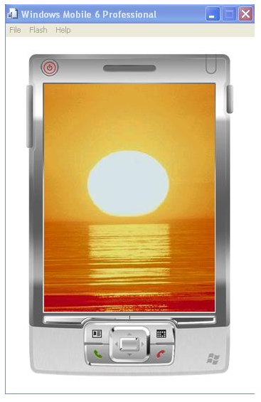
and
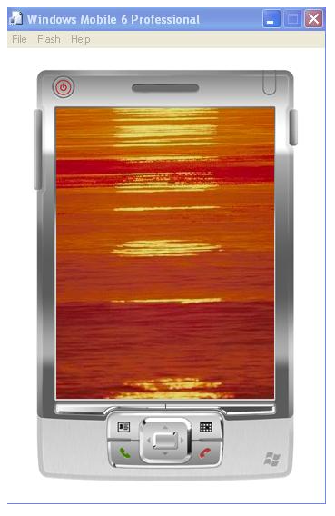
As you can see, I replaced the stale red and blue screens with something a bit more nice (: Well, obviously you know how to do that. Don’t you? (:
Some animation at last!Some animation at last!
Lets make the spaceship move! DirectDraw, Part 3
Again, make sure the image you cut is 320 pixels wide and 384 pixels high.
ddsd.dwFlags = DDSD_HEIGHT | DDSD_WIDTH;
ddsd.dwWidth = 320;
ddsd.dwHeight = 384;
hRet = g_pDD->CreateSurface(&ddsd, &g_pDDSOne, NULL);
if (hRet != DD_OK)
return InitFail(hWnd, hRet, szCreateSurfaceFailMsg);
Notice that the dimensions of the surface match the bitmap size, 320×384. Lets load the bitmap onto the surface now, in InitSurfaces():
DDCopyBitmap(g_pDDSOne, hbm, 0, 0, 320, 384);
So g_pDDSOne now points to a surface that holds our bitmap. Oh and one more thing, just declare a const variable to hold the number of columns in the image,
static const int TOTAL_COLS = 5;
Yes, you can go back and count (: Anyways, lets take a look at the UpdateFrame() function now:
static void UpdateFrame(HWND hWnd)
{
static BYTE phase = 0;
HRESULT hRet;
DDBLTFX ddbltfx;
RECT src, dest;
int row = 0, col = 0;
memset(&ddbltfx, 0, sizeof(ddbltfx));
ddbltfx.dwSize = sizeof(ddbltfx);
ddbltfx.dwFillColor = 0;
ddbltfx.dwROP = SRCCOPY;
//the destination rect is in the center of the screen
dest.top = 128;
dest.left = 88;
dest.bottom = 192;
dest.right = 152;
//clear the back buffer (color fill with black)
g_pDDSBack->Blt(&dest, NULL, NULL, DDBLT_COLORFILL | DDBLT_WAITNOTBUSY, &ddbltfx);
//calculate the src rect depending on the value of ‘phase’
row = phase/TOTAL_COLS;
col = phase%TOTAL_COLS;
src.top = 64*row;
src.left = 64*col;
src.bottom = src.top + 64;
src.right = src.left + 64;
while (TRUE)
{
hRet = g_pDDSBack->Blt(&dest, g_pDDSOne, &src, DDBLT_ROP, &ddbltfx);
if (hRet == DD_OK)
break;
if (hRet == DDERR_SURFACELOST)
{
hRet = RestoreAll();
if (hRet != DD_OK)
break;
}
if (hRet != DDERR_WASSTILLDRAWING)
break;
}
phase = (phase+1)%30;
}
#define TIMER_RATE 80
I took a small video of the rotating spaceship.